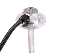
EPSILON ES Fuel level sensor is designed for precision (with accuracy <1%) measuring the level of fuel in reservoirs and vehicle fuel tanks. The sensor can be used in fuel economy control systems (control of fuel discharges and of fuel ups) and is satellite vehicle monitoring systems (GPS/GLONASS) of different manufacturers.
Unique differences from the sensors of other manufacturers:
More precise measurement of fuel level at the expense of a higher resolution sensor level and the best characteristics of linear measuring scale;
- Tech modular design (measuring head is mounted and dismantled independently of the fuel probe, which allows easy and quick to change, if necessary, the measuring head without re-calibration of the tank);
- The ability to use short-measuring probes (for flat tank depth of less than 30 cm);
- Light weight (300 g) and ease of installation.
Sensor Description
Inside the sensor measuring head is the level converter, digital signal processing circuit, the data exchange device, voltage regulator and circuit, providing the necessary protection for the input and output circuits. Connection with external devices is provided via cable.

The measuring of the fuel level is provided by the measuring head with the probe, which is immersed into fuel. The probe is a coaxial capacitor formed by an aluminum tube (outer electrode) and insulated copper string (inner electrode). The necessary tension of the string is supported by a spring which is located in a contact connector of the probe.
The mounting of the sensor is performed using self-drilling screws, flange fixing probe (together with a gasket) on the tank. Tightness of the measuring head is provided by O-ring seal located in the front groove.
Protection of the interface cable from mechanical effects is provided by a flexible metal hose.
Safety of the sensor is provided with the application of:
- intrinsically safe measuring circuit with normalized values of voltage, inductance, capacitance and resistance;
- multi-layered security and front-end supply chain;
- metal shell of the measuring head with a proper degree of protection (IP-68 according to GOST 14254);
- compound filling the shell of the measuring head.
Operation principle
Sensor probe immersed in the fuel acts as a variable capacitor, whose capacity is linearly dependent on the level of its filling with fuel.

The sensor measuring head performs a linear transformation, capacity of the probe into a digital code-level fuel, processing of the digital data by averaging the results of measurements, temperature measurement of fuel tank and issuance of data in a uniform protocol for EDE RS-485 or RS-232 or analog signals (only the level), depending on the model.
Data on the fuel level may be issued in the form of 10-and 12-or 16-bit value, the temperature data — in the form of an 8-bit value.
To determine the amount of the controlled fuel calibration procedure must be carried out on the fuel tank, in which we establish the relationship between the amount of fuel level to the sensor code level.
Calibration procedure is performed by specialists of RCS or its authorized dealers to install the sensor on the vehicle.
Installation of the sensor
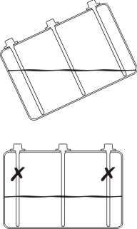
The sensor is mounted in the center fuel tank, as shown in the figure. Only in this case, the tilt acceleration or deceleration of the vehicle fuel level in the measuring point of the least subject to fluctuations. The probe should be oriented vertically downward.

Improper installation of the probe may cause loss of accuracy in determining the amount of fuel!
If the tank top difficult to obtain, it is necessary to remove the tank from the vehicle to perform proper installation the sensor.
The sensor is screwed into the threaded hole of the flange as shown in the figure. Tightness is ensured by a rubber O-ring groove located at the end of the measuring head.

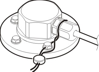
After the installation the sensor is sealed:

This how the proper installation of the fuel level sensor "Epsilon" looks like in practice, on a vehicle with two fuel tanks:
Tank calibration
To ensure accurate monitoring of fuel, the tank should be calibrated- initially empty (full) tank is filled (merged) in equal portions, with fuel, and with the help of special software eS Install it is measured and recorded by the sensor after adding (draining) the each serving.
To achieve the most accurate performance of the gauge is desirable to “train” the sensor. It is desirable to perform the calibration procedure not immediately after installing the sensor, but some time later, after the vehicle's mileage is corresponding with the expenditure of fuel in the 50 ÷ 70% of tank capacity. During this time, normalized by mechanical clearance, provided by a rubber gasket flange and a polymer sealant, and the entire surface of the probe forms a stable dielectric layer of fuel.
If the «training» of the sensor is not possible, then before the calibration of the tank, by the method of filling, using a new sensor (the probe) to immerse the probe into the fuel, remove and allow the fuel to drain for 20 −30 minutes. If the calibration is performed by draining, then the specified procedure is not needed. At the time of calibration of the sensor must be disconnected from the onboard controller and connected to the PC. At the end of the calibration connection to the onboard controller should be restored.
The result of calibration in the form of tank calibration tables and the credentials of the work performed is saved in PC format, which provides data transmission in the control software.
Attention! Calibration of the tank must be made using the same kind of fuel, which will be operated by the sensor (for example, can not be used for calibration of petrol, if you intend to operate with diesel fuel).
Technical characteristics
Digital| Description | Unit | Value | Notes |
|---|---|---|---|
| General | |||
| Valid values of electrical conductivity controlled by the fuel, not more then | S/m
|
10-8
|
2
|
| Temperatures range | °C | -40...+80 | |
| IP level protection of probe head | IP68 | Explosion proof certificate |
|
| Measurments | |||
| The range of measured values of the position of the controlled fuel | mm
|
From 10 to 910
|
1,3,4,5
|
| The resolution of the measurement of diesel fuel in the static mode, not worse then | mm
|
0,05
|
6
|
| The basic allowable error level measurement in a static mode, not more then | mm
|
0,5
|
7
|
| The average period of measurement results in dynamic mode | sec | 8 | |
| Bit code representation of measurement results | bit | 10/12/16 | Level (8) |
| 8 | Temperature | ||
| Power Supply | |||
| Supply voltage, the operating range | V | 7-50 | Rated |
| Current consumption | mA | 5,5±0,5 | At 12V |
| 2,5±0,2 | At 24V | ||
| Mode | Long | ||
| Acceptable impact of pulsed voltage on power circuits | ± 200V, 1sec ± 1100V, 1 msec |
9 | |
| Interface | |||
| Digital | RS-485 | Basic | |
| RS-232 | 10 | ||
| Analog | 11 | ||
| Installation size and weight | |||
| Execution of planting flange | SAE, 5 holes. d=5mm |
12 | |
| Type the thread probe | M25x1,5 | ||
| Size of the hexagon wrench for the measuring head | mm | 36 | According to GOST 6424 |
| The height of the measuring head over the surface of the tank, including the planting flange, not more then | mm | 29 | 13, 14 |
| Weight of the sensor, not more then | g | 300 | 4, 14 |
Notes to table 2:
- For diesel fuel with a nominal value of ε = 2.1 as adopted pursuant to the basic «620» (620mm).
- Allows measurements to grade fuel with a high electrical conductivity.
- The position of the upper (maximum) value of the measured level corresponds to the upper edge of the drain hole of the probe.
- Performance over «620» are performed as an option.
- Allowed the shortening of the probe «the place» no restrictions on minimum length.
- When using 16-bit representation of measurement results.
- Require further adjustment of the temperature dependence of the dielectric constant of controlled fuels.
- Adjustment is performed by the manufacturer to order the sensor.
- These are issued in two formats: 16 and 10/12 bit. Bit depth 10 or 12 bit software switchable.
- The default value — 12 bits. Satisfies the most stringent requirements of GOST 28751–90 (product class, the degree of hardness 4 to 24V on-board power supply).
- Possible on request.
- Possible execution on request with voltage output 0 — 5 V, current 0 — 20 mA or potentiometer.
- Other versions connecting flange and in agreement with the consumer.
- Does not include gasket. For specified performance of the flange.
